Lucas 14CUX Firmware / Tune Memory Addresses (Offsets)
The fuel data and software program are stored together with a combined size of only 16KB (16,384 bytes), the data and program together are then duplicated on the tune chip to full 32KB (32,768 bytes). The 14CUX’s CPU only accesses the second copy at prom file Offsets $4000 to $7FFF, but RoverGauge’s “Save Prom Image” option only saves a single copy to a Prom file with offsets $0000 – $3FFF. As a result I’ve listed both sets of prom offset addresses in the last table. Please note all of the following prom chip offsets / addresses start at the beginning of the prom file at offset $0000 and are not to be confused with the CPU’s internal addressing of C000 - FFFF. You can use the 14CUX Toolkit to duplicate the RoverGauge single copy ready for flashing to a chip, plus the 14CUXToolkit can fix the checksum if you’ve made your own changes directly in the file.
It’s important to note the location of the fuel data on the prom moved in 1993 for revision R2666 onwards, the old and new file offsets are listed in the first two tables below. In TunerPro you’ll see there are two sets of fuel tables, "R2422" tables for the older prom layout and the other tables are for the later R2666 on layout. The RoverGauge software is clever enough to automatically identify the correct location of the fuel map to display.
Fuel Map Offsets for Revision R2422 or earlier |
||||||
|
Contents |
Limp |
Map 1 |
Map 2 |
Map 3 |
Map 4 |
Map 5 |
|
Fuel Table Start |
$0000 |
$023F |
$0351 |
$463 |
$575 |
$0687 |
|
Multiplier (different CC) |
$0080 |
$02BF |
$03D1 |
$04E3 |
$05F5 |
$0707 |
|
Coolant warn up table |
$00B5 |
$02C1 |
$03D3 |
$04E5 |
$05F7 |
$0709 |
|
ADC Mux |
$0082 |
$0339 |
$044B |
$055D |
$066F |
$0781 |
|
AFM Table Row Scalar |
$01C9 |
$0349 |
$045B |
$056D |
$067F |
$0791 |
|
RPM Safety Delta |
|
$034A |
$045C |
$056E |
$0680 |
$0792 |
|
RPM Safety Limit |
|
$034B |
$045D |
$056F |
$0681 |
$0793 |
|
Map Last Byte |
|
$0350 |
$0462 |
$0574 |
$0686 |
$0798 |
Fuel Map Offsets for Revision R2666 on |
||||||
|
Contents |
Limp |
Map 1 |
Map 2 |
Map 3 |
Map 4 |
Map 5 |
|
Fuel Table Start |
$0000 |
$0267 |
$0379 |
$048B |
$059D |
$06AF |
|
Multiplier (different CC) |
$0080 |
$02E7 |
$03F9 |
$050B |
$061D |
$072F |
|
Coolant warn up table |
$00B5 |
$02E9 |
$03FB |
$050D |
$061F |
$0731 |
|
ADC Mux |
$0082 |
$0361 |
$0473 |
$0585 |
$0697 |
$07A9 |
|
AFM Table Row Scalar |
$01C9 |
$0371 |
$0483 |
$0595 |
$06A7 |
$07B9 |
|
RPM Safely Delta |
|
$0372 |
$0484 |
$0596 |
$06A8 |
$07BA |
|
RPM Safely Limit |
|
$0373 |
$0485 |
$0597 |
$06A9 |
$07BB |
|
Map Last Byte |
|
$0378 |
$048A |
$059C |
$06AE |
$07C0 |
Map 1-5 data length = 274bytes/112 hex (128 FuelTable + 2 Fuel scalar + 144)
Generic Fuel Data Setting |
||
|
Contents |
RoverGauge 16KB |
Full 32KB Chip
File |
|
Disable application of long term trim 00=Off; 80=On |
$00A0 |
$40A0 |
|
Overrun fuel cut minimum start $10 (1600rpm), $09 (2,700rpm) $08 (3,000), $07 (3,400), $06 (4,000rpm), $05 (4,800rpm) |
$0137 |
$4137 |
|
Neutral gear idle increase |
$0159 - $015A |
$4159 - $415A |
|
A/C idle increase |
$015B - $015C |
$415B - $415C |
|
Base idle |
$0176 - $0177 |
$4176 - $4177 |
|
AFM Row centre offset |
$01C7 - $01C8 |
$41C7 - $41C8 |
|
Heated screen idle increase |
$01E9 - $01EA |
$41E9 - $41EA |
|
HiRPMAdcMux |
$0231 - $023E |
$4231 - $423E |
|
Disable Tune resister (north USA) Locked = FF, unlocked 00 |
$07C1 |
$47C1 |
|
MIL On = FF, Off = 00 |
$07C2 |
$47C2 |
|
Start of the program code |
$0800 |
$4800 |
|
RPM Set Points Table |
$0800 - $083F |
$4800 - $483F |
|
Road Speed Comparator for different sensors (Offset varies) |
$1409 (R3652) |
$1323 (R2967) |
|
Engine Tuner/Builder ID if not FF |
$3D0E |
$7D0E |
|
Revision ID |
$3FE9 - $3FEA |
$7FE9 - $7FEA |
|
Checksum fixer (See note below) |
$3FEB |
$7FEB |
|
Tune ID |
$3FEC - $3FED |
$7FEC - $7FED |
|
Processor's reset vector |
$3FFE - $3FFF |
$7FFE - $7FFF |
AFM Row Table Scalar & AFM Row centre offset
When using a larger AFM you can improve the bottom row usage and move the idle row by adjusting the AFM Table Row Scalar & AFM Row centre offset (in TunerPro see TABLE 1-5 MAF Scalar & TABLE 1-5 MAF Scalar Offset). The scalar increases/decrease the scale of the rows and the offset move the mid point of the rows up and down.
RPM Set Points Table
|
RPM set points should be extended to 6250 RPM for TVRs or to the red line of your engine so that you have mixture control past 5500 RPM. The rpm set points are arranged in 4 columns starting at prom offset $800 with the highest RPM first. The first 2 columns of the table are the 16-bit RPM set points represented as the spark period (2 uSec units) and the 3rd and 4th columns are used to keep the AFR smooth between the set points.
If you want to create your own RPM set points do not simply raise the top bracket but spread the difference out over several brackets and the 3rd and 4th columns will probably require changing along with the 16-bit period value. For further information please see the readme file for the RPM Table Simulation tool that can be used to test different RPM set points. |
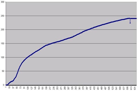
RPM Table with Glitch that caused ARF Glitch above
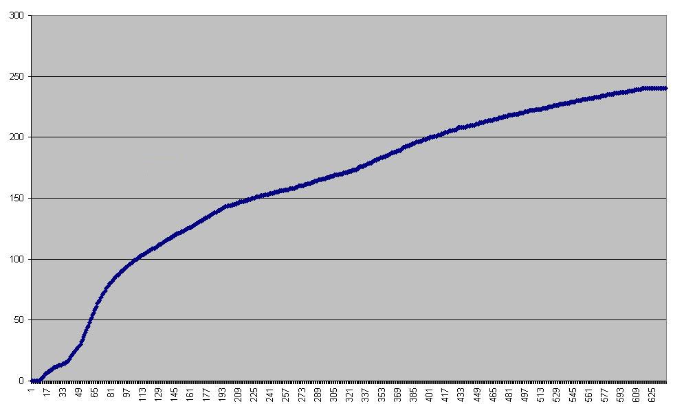
Smooth RPM Table to 6250
|
Checksum Fixer
Every time the ignition is first turned on the ECU program reads though the entire prom chip calculating the checksum to determine if the map is corrupt or been hacked. If the checksum isn’t correct the checksum error code is set which is merely an indication that the prom file has been altered and is not the code of death unless your prom is badly corrupt. Therefore after updating the prom file with TunerPro the equation below is used to calculate a new checksum fixer to a void the checksum error. The checksum can also be fixed with the 14CUX Toolkit described on the gadgets page.
New Checksum Fixer = Old Checksum Fixer - Sum of all bytes in bin file + 1
CO Trim screw adjustment
For non-cat vehicles it very important for smooth running the CO trim voltage is set correct for the different tunes. The CO trim adjustment is via 7/32 Allen key on the side of the AFM and basically the ECU supplies 5v and the variable resister in the AFM pulls the voltage down to ground. Please note RoverGauge only show the live CO trim adjustment once the engine is running or stalled by turning the ignition turning off long enough to allow the engine stop and then quickly back on again.
TEMPERATURE FUEL MULTIPLIER matrix
The column headings for the MAP TEMPERATURE FUEL MULTIPLIER matrix (0x00, 0x36, 0x56, 0x145, 0x171, 0x194, 0x224, 0x238)
on the left refers to hot temp and on the right refer to cold temp.
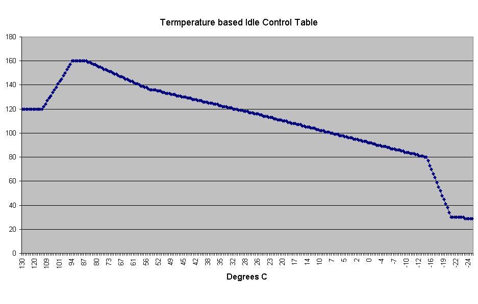
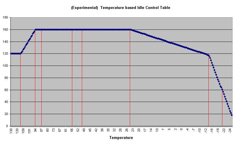
Coolant Temperature based Idle Control Simulator Program
www.stevesprint.com/remap-14cux/Coolant_Idle_Ctrl_Simulator.zip
|
Land Rover 3.9
|
Steve Lower Cold Idle
|
Disable Long Term Trim
If you want to re-map a cat map with without lambda control Mark Blitzracing has proved you can copy map 5 with multiplier to map2 then work on map 2 with the CO trim set to the mid point of 1.25 volts which equals lambda trim 0%. When finished simply copy the remapped map 2 back to map 5.
In addition Lucas actually provided a means of turning off long term trim by changing the “Disable application of long term trim” byte. The value at prom offset $00A0 is normally $80 but changing this to $00 (clearing bit 7) the application of the long term trim is bypassed. The long trim is still calculated and displayed by RoverGauge but is simply not be added to the fuel value. Interesting as the trim is calculated as normal and not applied the ECU keeps adding more and more trim until it hits 100%. Please note when setting $00A0 to 00 we are current not sure if the short trim is still calculated and applied.
ADCMux & HiRPMAdcMux to remove Road Speed Limiter
|
AdcMux stands for Analogue to Digital Multiplexer and is a list of sensors that the program uses to control the order the input sensors are read. Each map has its own AdcMux plus their is an additional power up AdcMux list that explains why the CO trim is not read until the engine fires up. While the rpm are above 4185 and the throttle is more than 70% the software uses the special HiRPMAdcMux table in place of the current maps AdcMux table that is heavily loaded with road speed measurements, the 87s. Lucas had a lot of trouble with the road speed limit and the High RPM MuxTable was possibly another patch to try to make the thing work correctly. The actual road speed limiter is in the program code and not the data section. TVR remove the road speed sensor from this list for precats to disable the road speed limiters but on later cars TVR reverted back to the Land Rover HiRPM AdcMux containing the limiter and bypassed the limiter in the program code that works at all RPM. The actually road speed limit is set in the code and it’s location varies between revisions, try look at the value at $2A41 and if it's $C4 then that is the limit in KPH (196 KPH or 122 MPH). |
Input Sensor Numbers87 - Road speed transducer 86 - Air con load input 02 - Air flow sensor (main signal) 03 - Throttle pot 84 - Coolant temp sensor 8D - O2 Reference Voltage 88 - Main relay voltage 8B - Fuel temp sensor 80 - Inertia switch 85 - Auto neutral switch 81 - Heated screen sense 09 - CO Trim screw 8E - Diagnostic plug |
Map |
AdcMux List |
|
2 (non cat) |
$87,$86,$02,$03,$84,$02,$8D,$88,$02,$8B,$80,$85,$81,$09,$8E,$FA |
|
5 (cat) |
$87,$86,$02,$03,$84,$02,$8D,$88,$02,$8B,$80,$85,$81,$8E,$FA,$FA |
|
Year |
Firmware |
Limiter |
Hi RPM Adc Mux |
|
TVR 1992 |
R2422 |
Removed |
8B 86 02 03 84 02 8D 88 02 8B 80 85 81 FA |
|
LR 1991 |
R2422 |
Limited |
87 02 87 86 87 02 87 87 87 87 87 87 87 F7 |
|
LR 1994 |
R3833 |
Limited |
87 02 87 86 87 02 87 87 87 87 87 87 87 F7 |
|
TVR 1993on |
R2967 |
Limited |
87 02 87 86 87 02 87 87 87 87 87 87 87 F7 |
Tunes resistors
|
Wire Colour |
Ohms |
Catalyst |
Application |
|
Red |
180 |
No |
Australian 3.5 & 3.9 |
|
Green |
470 |
No |
Europe & UK 3.9 (or 3.5 Disco) |
|
Yellow |
910 |
No |
Europe & UK 4.2 and Gulf States 3.9 |
|
Blue |
1800 |
Yes |
Europe & UK 4.2 and Gulf States 3.9 |
|
White |
3900 |
Yes |
Europe & UK 3.9 (or 3.5 Disco) |
USEFUL LINKS
http://www.g33.co.uk/fuel_injection.htm
http://www.rhel.co.uk/articles/fabrrc/fabrrc.htm
http://www.rv8r.co.uk/standardecu1.html
http://www.pirate4x4.com/forum/land-rover/1660129-after-market-injection-4-6v8-2.html
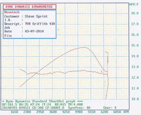
Demonstrates glitches in the rpm table causes glitches in the ARF
Diagnostic socket plug is a Lucas-Rists 5-way TTS socket housing (female terminals) -
http://img.photobucket.com/albums/v686/paulmc0308/Electrical/Misc/i-350-51155224a.jpg
http://img.photobucket.com/albums/v686/paulmc0308/Electrical/Misc/ftdi_with_tts_rear-1.jpg
Original Instructions on Piston Heads (August 2013)
Original Overview (November 2013)